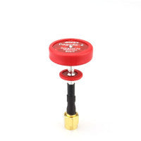
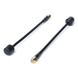
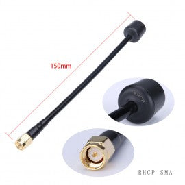
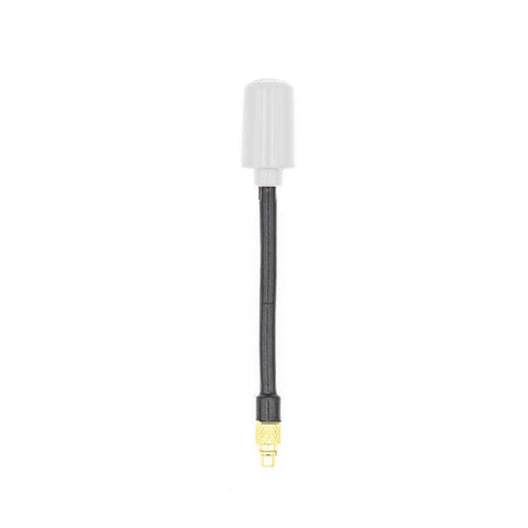
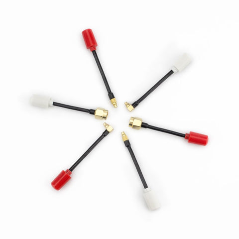
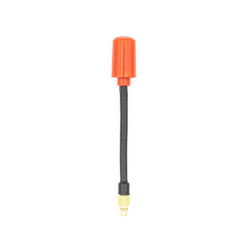
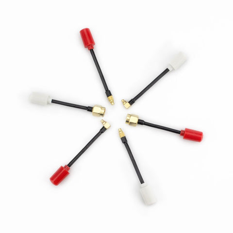
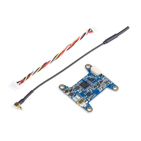
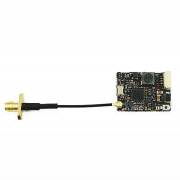
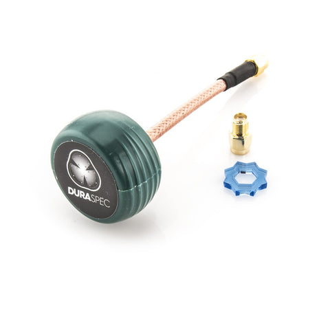
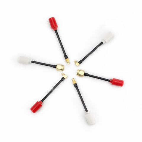
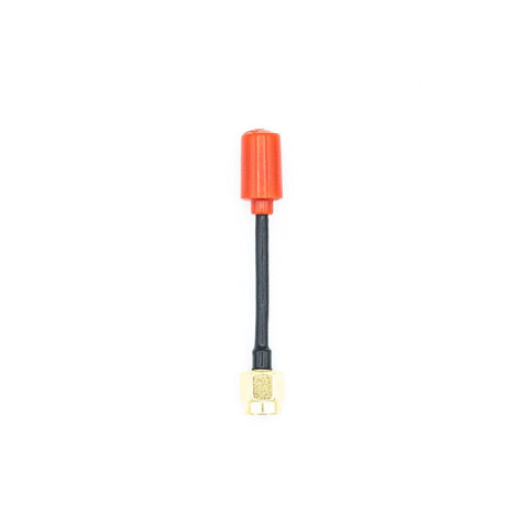
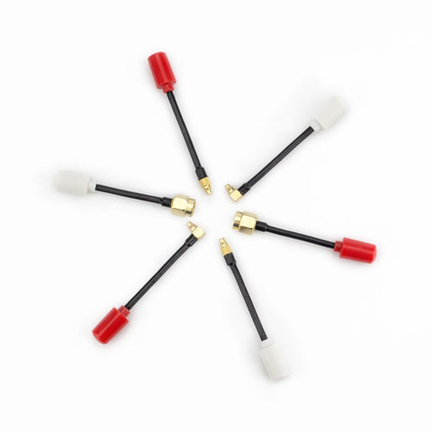
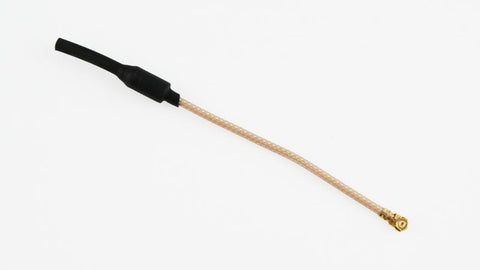
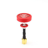
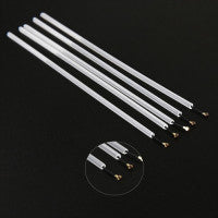
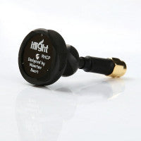
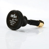
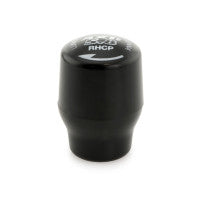
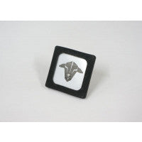
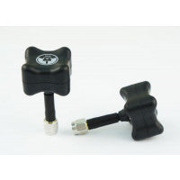
EMAX Pagoda 2 Antenna 5.8G 50mm RHCP SMA Red Omni FPV Flat Panel
SPECIFICATIONS
-
Center frequency: 5.8 GHz
-
Bandwidth: 500 MHz (5.55 – 6.05 GHz)
-
Matching: S11 < -20 dB, VSWR < 1.22 (at center frequency)
-
Axial ratio: < 1.3
-
Radiation efficiency: 95%
Originally the radiation efficiency was listed as 92%, this was a mistake. These values are based on simulation, actual measurements are below (they are very similar). The center frequency may shift a bit between batches as a result of variations in the dielectric constant of FR4. Also, not all brands of FR4 have the same dielectric constant. Frequency shifts up to 100 MHz are normal.
Radiation pattern

3D radiation pattern. Look at the 2D version if you actually want to see the numbers.

Simulation model.

Best case, vertical cross-section taken at various angles.

Worst case, vertical cross-section taken at various angles.

Simulation model.

Best case, vertical cross-section taken at various angles.

Worst case, vertical cross-section taken at various angles.
The 'best case' and 'worst case' correspond to different assumptions about what happens to signals that travel along the outside of the coax. In the 'best case' simulation, these are completely absorbed at the other end of the coax. In the 'worst case' simulation, they are completely reflected back towards the antenna. The latter case usually results in standing waves on the outside of the coax, which causes the coax itself to radiate and interfere with the radiation pattern of the antenna. This is why the radiation pattern isn't smooth anymore. The reality will be somewhere between these two extremes.
Measurements

VNA measurements.
Emax
Antenna
1 In Stock
SPECIFICATIONS
-
Center frequency: 5.8 GHz
-
Bandwidth: 500 MHz (5.55 – 6.05 GHz)
-
Matching: S11 < -20 dB, VSWR < 1.22 (at center frequency)
-
Axial ratio: < 1.3
-
Radiation efficiency: 95%
Originally the radiation efficiency was listed as 92%, this was a mistake. These values are based on simulation, actual measurements are below (they are very similar). The center frequency may shift a bit between batches as a result of variations in the dielectric constant of FR4. Also, not all brands of FR4 have the same dielectric constant. Frequency shifts up to 100 MHz are normal.
Radiation pattern

3D radiation pattern. Look at the 2D version if you actually want to see the numbers.

Simulation model.

Best case, vertical cross-section taken at various angles.

Worst case, vertical cross-section taken at various angles.

Simulation model.

Best case, vertical cross-section taken at various angles.

Worst case, vertical cross-section taken at various angles.
The 'best case' and 'worst case' correspond to different assumptions about what happens to signals that travel along the outside of the coax. In the 'best case' simulation, these are completely absorbed at the other end of the coax. In the 'worst case' simulation, they are completely reflected back towards the antenna. The latter case usually results in standing waves on the outside of the coax, which causes the coax itself to radiate and interfere with the radiation pattern of the antenna. This is why the radiation pattern isn't smooth anymore. The reality will be somewhere between these two extremes.
Measurements

VNA measurements.
Related Products
Albatross 5.8GHz RHCP FPV Antenna
PRODUCT DESCRIPTION Durable 5.8G antenna for Analog or Digital FPV. The perfect upgrade part for your DJI Air Unit to avoid buying fragile stock a...
RunCam Split Orange
RunCam Split Split RunCam 3 for FPV HD/FPV camera 1080p/60fps HD recording and WDR FPV CamExtremely Light WeightLow LatencyReal-time aud...
Albatross 5.8GHz 150mm RHCP FPV Antenna
PRODUCT DESCRIPTION Durable 5.8G antenna for Analog or Digital FPV. The perfect upgrade part for your DJI Air Unit to avoid buying fragile stock a...
Rush Tank Racing Edition 5.8GHz VTX w/ SmartAudio
The RUSH Tank Racing is a high-quality 5.8GHz VTX with strong anti-interference ability and stable transmission. Rush has removed the mounting hole...
EMAX Nano 5.8Ghz MMCX Straight Antenna - LHCP
Introducing the EMAX Nano FPV antenna. Engineered from the ground up for performance and size, the head of the Nano comes in at .85 grams of weight...
EMAX Nano 5.8Ghz MMCX Straight Antenna - RHCP
Introducing the EMAX Nano FPV antenna. Engineered from the ground up for performance and size, the head of the Nano comes in at .85 grams of weight...
ImmersionRC Tramp HV 5.8GHz Video Tx - (US Version)
The ImmersionRC Tramp HV 5.8GHz Video Tx is one of the most advanced 5.8GHz Video Transmitter available today. Only 4 grams, and a slender 31 x 20m...
Lumenier TX5GS 25-200-500mW 5.8GHz FPV Transmitter w/ BFCMS Control (MMCX)
The Lumenier TX5GS 25-200-500mW 5.8GHz FPV Video Transmitter w/ BFCMS Control is the perfect all around FPV VTX. This transmitter features the late...
TBS UNIFY PRO 5G8 LINEAR ANTENNA (MMCX)
A linear antenna with MMCX connector. SPECS Weight: 1.8grams Length: approximately 102mm (include shrink tube) Width: 1.79mm
Force 5.8GHz 48CH 0/25/100/200/400/600mW Switchable VTX With MMCX
Description:iFlight the Force 5.8G 48CH 0/25/100/200/400/600mW Switchable FPV Transmitter, support OSD Frequency and Power tuning. The output p...
TBS UNIFY HV / FRSKY RX MOUNTING BOARD
Allows a Team BlackSheep Unify Pro HV/HV-Race and receiver to be mounted on a board for a low profile and clean stacking solution. The pads allow y...
TBS Unify Pro HV (SMA)
The best VTX on the market has got gotten better! No more hard to manage 5V input like the smaller version Unify Pro.Take 2-6S lip and has a 5V cle...
RunCam Micro Eagle
123456 WDR level 1-6 available Mirror & Flip image available Dimension Package 1x Camera ...
IBCrazy 5.8 GHz LHCP Dura-Spec Antenna
An amazing creation is built by Alex Greve (IBCrazy). The Dura-Spec antennas are built extremely tough. This 5.8GHz antenna is left hand circular p...
Lumenier AXII Replacement Caps (LHCP) (2pcs)
A set of 2 Lumenier AXII Replacement Caps (LHCP) (2pcs)
iFlight 5.8Ghz FPV Antenna (58mm / RHCP / MMCX)
Specifications: Gain: 2.0Dbi Axial Ratio: <1.0 Weight: 3g (MMCX) Dimension: 47*11*17mm(MMCX) Interface: MMCX Polarization: RHCP SWR: <1.1 (O...
Fatshark Adjustable Earphones
Being able to hear your quad while flying improves your feel for what its doing and can immerse you even more in the experience. Fatshark adhusta...
Fat Shark Goggle Strap - Gives you Props
Custom Replacement Goggle strap compatible with all Fatshark base models, Dominator, Attitude, Teleporter, Predator and Skyzone Models. Designs ...
EMAX Nano 5.8Ghz SMA Antenna - LHCP
Introducing the EMAX Nano FPV antenna. Engineered from the ground up for performance and size, the head of the Nano comes in at .85 grams of weight...
EMAX Nano 5.8Ghz SMA Antenna - RHCP
Introducing the EMAX Nano FPV antenna. Engineered from the ground up for performance and size, the head of the Nano comes in at .85 grams of weight...
HGLRC Forward 5.8GHz 48CH 25/50/100/200/400mW VTX
Forward VTX is simulated 5.8GHz ISM band transmission with stable output power, long transmission distance, and strong power filter. Specification...
Rush Tank 5.8GHz VTX w/ SmartAudio
The RUSH Tank is a high-quality 5.8GHz VTX with strong anti-interference ability and stable transmission. The TANK has four adjustable levels of tr...
TBS UNIFY PRO 5G8 LINEAR ANTENNA (U.FL)
A linear antenna with IPX / U.FL connector compatible with the TBS UNIFY PRO 5G8 HV or U.FL connector compatible Video transmitters. In conjunctio...
Goggles for Bugs 8 / Bugs 8 Pro (ALL 2.4gHz Drones)
The G3 is unlike any other conventional FPV headset around in the sense that it doesn’t have its own built-in monitor. This is because it wa...
Lumenier AXII Patch Antenna 5.8GHz (RHCP)
The Lumenier AXII 5.8GHz Patch Antenna offers you the highest performance you can get from a mini patch antenna designed for FPV. The Lumenier AXII...
Super Mini Stubby 5.8GHz 5dbi RHCP Antenna
Super Mini Stubby 5.8GHz 5dbi RHCP Antenna Specifications: - Weight: 6.7g- Length:28mm- Gain: 5dBi- Axial Ratio:0.74- Frequency:5000-6000MHz-...
Matek 5.8G 40CH 25/200/500mW switchable Video Transmitter
Specifications & Features Input voltage: 7~27V(2~6S LiPo)40 standard channels, A/B/E/F/R BandOutput Power: 25, 200, 500mW switchableBEC Output:...
VAS CROSSHAIR (RHCP) 5.8GHZ
The Crosshair antenna is a 10dbic directional antenna with exceptionally high axial ratio (.98). Suitable for long distance transmission where rang...
TBS UNIFY 5V / FRSKY RX MOUNTING BOARD
Allows a Team BlackSheep Unify Pro V2 (5V only version) and receiver to be mounted on a board for a low profile and clean stacking solution. The pa...
TBS UNIFY PRO NANO 5G8
SIZE MATTERS! As builds become smaller and the innovation surrounding brushed and brushless micro quads accelerates, the need for a high-quality V...
Lumenier AXII Stubby 5.8GHz Antenna (LHCP)
The Lumenier AXII Stubby 5.8GHz Antenna takes all the same technology of the full size AXII and shrinks it down to less than half the size! Lumenie...
Lumenier AXII Replacement Caps (RHCP) (2pcs)
A set of 2 Lumenier AXII Replacement Caps (RHCP) (2pcs)
TBS UNIFY PRO 5G8 V3 (SMA)
The smallest and most powerful (800mW!) video transmitter the world has ever seen! It's race ready with PitMode, a super-clean and interference fre...
Matek FCHUB-VTX W/5.8G VIDEO TRANSMITTER
Specifications & Features Input voltage: 6~27V(2~6S LiPo) PDB: 4*30A (4*46A, 5 seconds) Current Sensor: 184A (Scale 179) BEC Output: 5V/1A for...
EMAX Pagoda 2 Antenna 5.8G 50mm RHCP RP-SMA Red Omni FPV Flat Panel
SPECIFICATIONS Center frequency: 5.8 GHz Bandwidth: 500 MHz (5.55 – 6.05 GHz) Matching: S11 < -20 dB, VSWR < 1.22 (at center f...
Plastic Protective Tube for 2.4G Antenna 2pc
Description Protective tubing for your RX antenna wires against prop inpact and other damage. Details - Size: 15 x 2.5mm (1.5mm inner diamete...
Iflight Pagoda-2 5.8G Omni Antenna RHCP 50mm SMA
Pagoda-2 5.8G FPV Omni Antenna RHCP 50mm Features: Light Weight Extremely Durable Smaller than current omni antennas Nearly Perfect axial ...
Iflight Pagoda-2 5.8G Omni Antenna RHCP 50mm RP-SMA
Pagoda-2 5.8G FPV Omni Antenna RHCP 50mm Features: Light Weight Extremely Durable Smaller than current omni antennas Nearly Perfect axial ...
Lumenier AXII Stubby 5.8GHz Antenna (RHCP)
The Lumenier AXII Stubby 5.8GHz Antenna takes all the same technology of the full size AXII and shrinks it down to less than half the size! Lumenie...
Eachine VR-007 Pro 5.8G 40CH HD FPV Goggles 3.7V 1600mAh Battery
Product Specification: Dimension(mm) : 151x177x103 Weight : 217g(battery not included) Battery Weight : 24g Screen Size ...
Eachine-ROTG01 5.8G 150CH FPV Receiver For Android
Eachine ROTG01 UVC OTG 5.8G 150CH Full Channel FPV Receiver For Android Mobile Phone Smartphone Which Support UVC OTG OnlyDescription : Eachine ROT...
Eachine VR D2 Pro Upgraded FPV Goggles with DVR
Specification: Brand name: Eachine Item name: VR D2 Pro FPV Goggles Screen size: 5 inches Screen resolution: 800x480 Frequency channel: buil...
TBS 5G8 LHCP PATCH (SMA)
Manufactured by Team BlackSheep, this antenna is your cheap entry into circular polarization. The 5dbi gain provides enough beamwidth to comfortabl...
Foxeer 5.8G 60mm 4 Leaf Cover AntennaSMA Male-Red
Foxeer 5.8g 60mm 4 Leaf Cover Antenna SMA Male Features: Frequency range:5600-5950MHz Gain :3DBi SWR:<1.5 Direction:omni Max power :50w ...
Foxeer 5.8G 60mm 4 Leaf Cover AntennaSMA Male-Blue
Foxeer 5.8g 60mm 4 Leaf Cover Antenna SMA Male Features: Frequency range:5600-5950MHz Gain :3DBi SWR:<1.5 Direction:omni Max power :50w ...
Foxeer Raceband 5.8G 40CH TM25 25mW SMA
Type TM25 SWITCHER Frequency(MHz) FM Video format NTSC/PAL Output Impedence 50 Ohm ...
TBS TRIUMPH-STUB RPSMA (2 Pack)
While other antennas rely on copycat designs the TBS Triumph takes a giant leap in 5.8 GHz antenna technology. Video Aerial Systems LLC (IBcrazy) a...
TBS TRIUMPH SMA (2 Pack)
While other antennas rely on copycat designs the TBS Triumph takes a giant leap in 5.8 GHz antenna technology. Video Aerial Systems LLC (IBcrazy) a...
VAS 5.8GHz ION Antenna (RHCP)
Details The Ion antenna is a high gain Circularly Polarized omnidirectional antenna with near perfect axial ratio. The Ion’s compact size and li...

